This project is a collaborative build of a fully functional slot machine using an Arduino microcontroller. Our team — Wiktor, Mateusz, and Moamen — is developing it as part of our Microcontroller Programming coursework. The idea is to simulate a classic slot machine using hardware components and embedded logic, incorporating user input, feedback loops, and interactive sound and visuals.
motivation
The project was born out of our shared interest in:
-
Building something fun and rewarding with embedded systems
-
Gaining hands-on experience with motors, sensors, and signal control
-
Exploring how real-time user interaction can be implemented with Arduino
-
Making our Microcontroller class more exciting (and chaotic) - main motivation
Also — who doesn’t love the thrill of a slot machine?
theory
The slot machine operates on basic embedded system principles:
-
Input: A potentiometer simulates the “lever” action, read through an analog input pin.
-
Processing: The Arduino reads the input, starts the motor, and triggers a musical sequence.
-
Output:
-
A servo motor spins the slots
-
A buzzer plays Faded by Alan Walker
-
Color detectors check the slots after the spin
-
An LCD screen displays messages — including the ultimate JACKPOT!
-
We aim to combine hardware control and timing with user feedback, ensuring synchronization between spin, music, and result evaluation.
tech stack
-
Arduino Uno (main board)
-
Potentiometer (input control)
-
DC Motor (spins the slots)
-
Photoresistors / Color Detectors (detect slot symbols)
-
LCD 16x2 Display (shows results)
-
Piezo Buzzer (plays music)
-
Breadboards, resistors, jumper wires (for circuit building)
progress logs
- 2025-05-27: We brainstormed the main components and divided responsibilities
- 2025-05-29: Wiktor successfully got the buzzer to play Faded — vibes confirmed.
- 2025-06-04: We menaged to assemble a semi-final version of wiring, changed servo motor into DC motor.
- 2025-06-05: Color detection working!
- 2025-06-09: Final assembly is upon us - everything seems to be in order and working…
- 2025-06-11: Last minuts on the project, tommorow - the grand reveal during the labs. Most things are working…
technical difficulties:
- DC motor cannot be plugged directly into arduino and we are missing a transistor - we have to manually turn it on and off - unsatisfactory.
- Color detection works through a simple heuristic and a series of if-elses with the green being the last if before “Unknown” - thus green detection is buggy. Overall, any color detection with these is buggy, sometimes it works sometimes it doesn’t.
- The box that the project is in could have some better aesthetics and fitting for all the parts.
summary
code
#include <Wire.h> // Library for I2C communication
#include <LiquidCrystal_I2C.h> // Library for I2C LCD display #include <pitches.h> // Library with musical note frequencies
LiquidCrystal_I2C lcd(0x27, 16, 2); // Initialize LCD at I2C address 0x27, 16 columns, 2 rows

// Define pin numbers for color sensor control and output
#define s0 8
#define s1 9
#define s2 10
#define s3 11
#define motorPin 12 // Pin that controls the motor (spinning effect)
#define out1 5 // Sensor 1 output pin
#define out2 6 // Sensor 2 output pin
#define out3 7 // Sensor 3 output pin
const int potentiometerPin = A0; // Analog input pin for potentiometer

// Melody notes to be played during spin effect
int melody[] = { NOTE_F4, NOTE_F4, NOTE_F4, NOTE_A4, NOTE_D4, NOTE_D4, NOTE_D4, NOTE_C4, NOTE_A4, NOTE_A4, NOTE_A4, NOTE_A4, NOTE_E4, NOTE_E4, NOTE_E4, NOTE_D4 };

// Duration values corresponding to melody notes
int noteDurations[] = { 4, 4, 4, 4, 4, 4, 4, 4, 4, 4, 4, 4, 4, 4, 4, 4 };

// Time tracking for non-blocking loop (unused now, but good practice)
unsigned long previousMillis = 0; const unsigned long interval = 50; // Interval to check potentiometer value

// Flags and variables
bool effectActive = false; // Flag to trigger spin & color reading
bool isPlaying = false; // Tracks whether music is currently playing
int lastPotValue = 0; // Last recorded potentiometer value

// Structure to hold RGB color readings struct
Rgb { int red; int green; int blue; };

void setup() {
	Serial.begin(9600); // Start serial monitor for debugging

	pinMode(s0, OUTPUT); // Set up pins controlling the color sensor
	pinMode(s1, OUTPUT);
	pinMode(s2, OUTPUT);
	pinMode(s3, OUTPUT);
	pinMode(out1, INPUT); // Set color sensor output pins as inputs
	pinMode(out2, INPUT);
	pinMode(out3, INPUT);
	pinMode(motorPin, OUTPUT); // Motor pin as output

	digitalWrite(s0, HIGH); // Set frequency scaling for sensor
	digitalWrite(s1, HIGH);
}
void readPotentiometer() { // Read current potentiometer value and check for significant change
	int currentPotValue = analogRead(potentiometerPin);
	if (abs(currentPotValue - lastPotValue) > 200) {
		Serial.print("Potentiometer: ");
		Serial.println(currentPotValue);
		lastPotValue = currentPotValue; // Update last known value
		effectActive = true; // Trigger effect on large change
	}
}
void playSpinEffect() { // Play music and turn motor on/off every other note for visual effect
	isPlaying = true;
	for (int i = 0; i < 16; i++) {
	if (i % 2 == 0) digitalWrite(motorPin, HIGH); // Motor ON for even notes
	else digitalWrite(motorPin, LOW); // Motor OFF for odd notes
	int duration = 2500 / noteDurations[i]; // Calculate note duration
	tone(3, melody[i], duration); // Play note on pin 3
	delay(duration * 1.05); // Wait until note finishes
	noTone(3); // Stop playing note
	}
	digitalWrite(motorPin, LOW); // Ensure motor is off at end
	isPlaying = false;
}
Rgb getColors(int outPin) { // Measure RGB values from color sensor connected to given output pin
	Rgb color;
	digitalWrite(s2, LOW);
	digitalWrite(s3, LOW);
	color.red = pulseIn(outPin, digitalRead(outPin) == HIGH ? LOW : HIGH); // Measure red
	delay(20);
	digitalWrite(s3, HIGH);
	color.blue = pulseIn(outPin, digitalRead(outPin) == HIGH ? LOW : HIGH); // Measure blue
	delay(20);
	digitalWrite(s2, HIGH);
	color.green = pulseIn(outPin, digitalRead(outPin) == HIGH ? LOW : HIGH); // Measure green
	delay(20);
	return color;
}
String getStableColor(int outPin, int repeatCount = 5) {
	String lastColor = "";
	int sameCount = 0;
	while (sameCount < repeatCount) {
		RGB rgb = getColors(outPin);
		String currentColor = classifyColor(rgb);
		if (currentColor == lastColor && currentColor != "Unknown") {
			sameCount++;
		} else {
			sameCount = 1; // reset
		lastColor = currentColor;
		}
		delay(50);
	}
	return lastColor;
}
String classifyColor(Rgb c) { // Convert raw RGB values into a named color using simple heuristics
	if (c.red <= 15 && c.green <= 15 && c.blue <= 15) return "White";
	else if (c.red < c.blue && c.red <= c.green && c.red < 23) return "Red";
	else if (c.blue < c.green && c.blue < c.red && c.blue < 20) return "Blue";
	else if (c.green < c.red && (c.green - c.blue <= 8)) return "Green";
	else return "Unknown";
}
void showEffect(String color1, String color2, String color3) {// Display result of color comparison on LCD
	lcd.init();
	lcd.backlight();
	lcd.setCursor(0, 0);
	lcd.print("sUpEr JaCkPoT");
	delay(3000); // Show splash screen for fun
	lcd.clear();
	lcd.setCursor(0, 0);
	if (color1 == color2 && color2 == color3) {
		lcd.print("Win"); // All three sensors detected same color
	} else {
		lcd.print("Lose"); // At least one color is different
	}
}
void loop() { // Main program loop
	unsigned long currentMillis = millis(); // Get current time (for future expansions)
	readPotentiometer(); // Check if potentiometer was turned
	if (effectActive) {
		playSpinEffect(); // Play sound and motor effect
// Read RGB values from all three sensors
		Rgb rgb1 = getColors(out1);
		Rgb rgb2 = getColors(out2);
		Rgb rgb3 = getColors(out3); // Convert raw RGB to color names

		String color1 = getStableColor(out1);
		String color2 = getStableColor(out2);
		String color3 = getStableColor(out3);

// Debug output to Serial Monitor
		Serial.print("C1: ");
		Serial.println(color1);
		Serial.print("C2: ");
		Serial.println(color2);
		Serial.print("C3: ");
		Serial.println(color3);
		showEffect(color1, color2, color3); // Show result on LCD
		effectActive = false; // Reset effect trigger
	}
}
wiring (courtesy of mateusz)
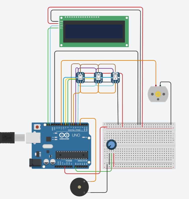 |
|---|
| A veeery simplified wiring :) |
lessons learned
-
What starts as a simple “digital output HIGH” in class becomes a whole different beast when you’re wiring a real DC motor in a shoebox. This project pushed me to apply textbook concepts — signal timing, voltage thresholds, component tolerance — in real-world conditions where perfection is optional and duct tape is king.
-
There’s nothing like watching your circuit fail because you didn’t include a transistor. Working with motors taught me more than just electronics — it taught me respect for safe power delivery and how one small oversight can compromise your entire setup. Lesson learned: always plan your circuit like it wants to explode.
-
Sensors don’t behave like the datasheets promise — especially not when ambient light, electrical noise, and sketchy jumper wires get involved. This project forced me to embrace iterative debugging, patience, and the joy of realizing that the problem wasn’t your fault this time. Probably.
-
No PCB? No proper motor driver? No problem. I built the prototype with what I had — a shoebox, a soldering iron, and some stubbornness. It was the perfect reminder that engineering is creativity under constraints, and good design starts at “minimum viable” before it gets fancy.
-
Everything might work perfectly on its own, but once you combine it all… chaos. I learned the hard way that system integration needs its own love: wiring stability, power distribution, fallback logic, even basic UX if you want people to use it without panic. Building a device means building an experience.